Mobile Application >>Hydrostatic Transmission Pumps & Motors |
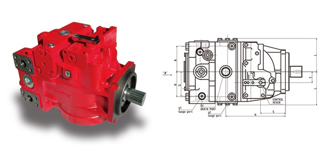
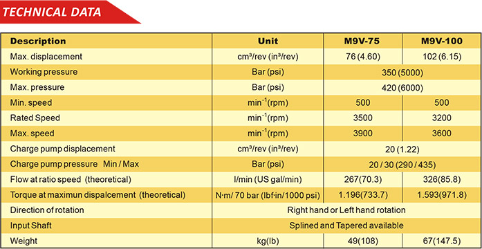
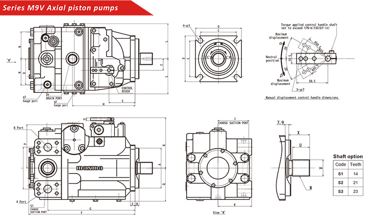
 |
Hydrostatic Transmission Pumps |
|
|
| Technical data |
|
Dimension |
Frame size |
| 33 |
52 |
70 |
89 |
119 |
166 |
334 |
| Displacement per revolution |
cc / rev. |
33.3 |
51.6 |
69.8 |
89 |
118.7 |
166.8 |
333.7 |
| Max. pressure (continuous) |
bar |
350 |
| Nominal pressure |
bar |
210 |
| Theoretical specific torque |
Nm / bar |
0.53 |
0.82 |
1.11 |
1.42 |
1.89 |
2.64 |
5.31 |
| Max. Speed |
rev /min |
3600 |
3100 |
2900 |
2600 |
2400 |
2100 |
1670 |
| Max. case pressure |
bar |
2.5 (constant) - 5 (peak) |
| Boost pressure |
bar |
11 \ 25 |
| Moment of inertia |
Kgm² |
0.004 |
0.008 |
0.012 |
0.018 |
0.029 |
0.05 |
0.161 |
| Kinetic viscosity range |
cSt |
12 - 1000 |
| Optimum kinetic viscosity range |
cSt |
25 - 36 |
| Working fluid |
|
Mineral oil |
| External temperature |
℃ |
minus 40 - plus 25 |
| Max. temperature of working fluid |
℃ |
plus 80 |
| Purity class of working fluid |
ISO 4406 |
18 / 13 |
| Max. swashlate angle |
Degrees |
18° |
| Weight |
kg |
30 |
35 |
40 |
47 |
70 |
124 |
197 |
|
|
| Order Code |
| This order code describes the desired model variant of an axial piston pump |
| PV |
|
MH |
|
\ |
20 |
|
|
|
|
|
|
1 |
2 |
3 |
4 |
5 |
6 |
7 |
8 |
9 |
10 |
11 |
12 |
|
|
| 1=Design |
|
| 2=Frame Size |
| Displacement pre revolution: |
33=33.3cc |
52=51.6cc |
70=69.8cc |
89=89cc |
119=118.7cc |
166=165.8cc |
334=333.7cc |
|
|
|
| 3=Displacement Control |
| MH=Mechanical Displacement Control |
|
| 4=Direction of rotation |
| R=clockwise L=conterclockwise |
|
| 6=Serie |
| 20=series 20 for closed circuit |
|
7=Type of input shaft
( NOTE: S=standard
A=available on request ) |
|
33 |
52 |
70 |
89 |
119 |
166 |
334 |
| A=14 theeth 12/24 pitch. (31.2 mm) |
A |
A |
A |
A |
|
|
|
| B=19 theeth 16/32 pitch. (31.75 mm) |
A |
A |
A |
A |
|
|
|
| C=21 theeth 16/32 pitch. (34.5 mm) |
S |
S |
S |
A |
A |
A |
|
| D=23 theeth 12/24 pitch. (37.68 mm) |
|
|
|
S |
|
|
|
| E=27 theeth 16/32 pitch. (44.03 mm) |
|
|
|
A |
S |
S |
|
| F=40 theeth 16/32 pitch. (64.66 mm) |
|
|
|
|
|
|
S |
| G=13 theeth 8/16 pitch. (44.71 mm) |
|
|
|
A |
A |
A |
A |
| H=15 theeth 8/16 pitch. (50.60 mm) |
|
|
|
|
|
|
A |
| I=20 theeth 16/32 pitch. (50.6 mm) |
A |
A |
A |
A |
|
|
|
| J=cone, 1:8 SAE J501, (41.27 mm) |
|
|
|
A |
A |
A |
|
| K=cone, 1:8 SAE J501, (31.75 mm) |
A |
A |
A |
A |
|
|
|
| L=cylindrical dyam. 34.925 |
A |
A |
A |
|
|
|
|
| M=cylindrical dyam. 44.45 |
|
|
|
A |
A |
A |
|
| O=cylindrical dyam. 63.5 |
|
|
|
|
|
|
A |
|
|
|
8=Pressure inlet ports A,B
( NOTE: S=standard
A=available on request ) |
|
33 |
52 |
70 |
89 |
119 |
166 |
334 |
| A=SAE j518c, size 1", 6000 psi |
A |
A |
A |
A |
A |
|
|
| B=SAE j518c, size 1", 5000 psi |
S |
S |
S |
S |
S |
|
|
| C=ISO 6162 DN 25 |
A |
A |
A |
A |
A |
|
|
| D=SAE j518c, size 1 1/2", 6000 psi |
|
|
|
|
|
S |
S |
|
|
|
9=Charge pump
( NOTE: S=standard
A=available on request ) |
|
33 |
52 |
70 |
89 |
119 |
166 |
334 |
| A=8.2cc |
A |
|
|
|
|
|
|
| B=12.3cc |
S |
S |
A |
A |
|
|
|
| C=18.03cc |
A |
A |
S |
S |
|
|
|
| D=18.85cc |
|
|
|
|
S |
|
|
| E=32.8cc |
|
|
|
|
A |
S |
|
| F=65.5cc |
|
|
|
|
|
A |
S |
| G=8.2 + 8.2cc |
A |
|
|
|
|
|
|
| H=12.3 + 8.2cc |
A |
A |
|
|
|
|
|
| I=18.03 + 8.2cc |
|
|
A |
A |
|
|
|
| N=withoutchange pump |
A |
A |
A |
A |
A |
A |
A |
|
|
|
| 10=change pump press |
13=13 bar other charge pressure setting on request |
| 11=Control orfice pag.4 |
N=without orifice |
A=0.76 mm |
B=0.91 mm |
C=1.05 mm standard |
D=1.36 mm |
E=1.6 mm |
|
|
|
| 12=available for special request |
|
|
|
|
|
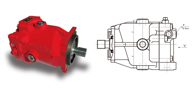
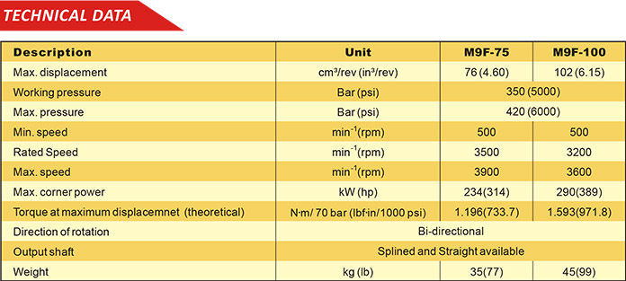
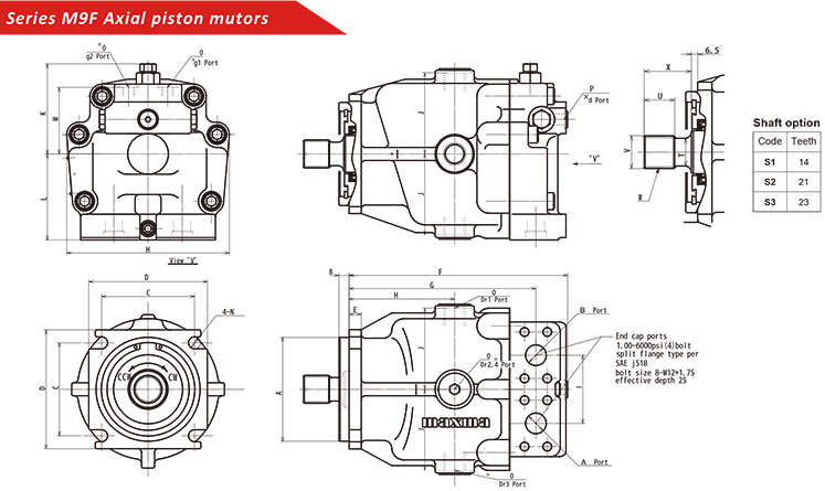
Axial Piston Fix Displacement Motor |
|
|
| Technical data |
|
Dimension |
Frame size |
| 33 |
52 |
70 |
89 |
119 |
166 |
334 |
| Displacement per revolution |
cc / rev. |
33.3 |
51.6 |
69.8 |
89 |
118.7 |
166.8 |
333.7 |
| Max. pressure (continuous) |
bar |
350 |
| Nominal pressure |
bar |
210 |
| Theoretical specific torque |
Nm / bar |
0.53 |
0.82 |
1.11 |
1.42 |
1.89 |
2.64 |
5.31 |
| Max. Speed |
rev /min |
3600 |
3100 |
2900 |
2600 |
2400 |
2100 |
1670 |
| Max. case pressure |
bar |
2.5 (constant) - 5 (peak) |
| Boost pressure |
bar |
11 \ 25 |
| Moment of inertia |
Kgm² |
0.004 |
0.008 |
0.012 |
0.018 |
0.029 |
0.05 |
0.161 |
| Kinetic viscosity range |
cSt |
12 - 1000 |
| Optimum kinetic viscosity range |
cSt |
25 - 36 |
| Working fluid |
|
Mineral oil |
| External temperature |
℃ |
minus 40 - plus 25 |
| Max. temperature of working fluid |
℃ |
plus 80 |
| Purity class of working fluid |
ISO 4406 |
18 / 13 |
| Max. swashlate angle |
Degrees |
18° |
| Weight |
kg |
30 |
35 |
40 |
47 |
70 |
124 |
197 |
|
|
| Order Code |
| This order code describes the desired model variant of an axial piston pump |
| MF |
|
V |
\ |
20 |
|
|
|
|
|
|
|
1 |
2 |
3 |
4 |
5 |
6 |
7 |
8 |
9 |
10 |
11 |
12 |
|
|
| 1=Design |
|
| 2=Frame Size |
| Displacement pre revolution: |
33=33.3cc |
52=51.6cc |
70=69.8cc |
89=89cc |
119=118.7cc |
166=165.8cc |
334=333.7cc |
|
|
|
| 3=Displacement Control |
|
| 5=Serie |
| 20=series 20 for closed circuit |
|
6=Type of input shaft
( NOTE: S=standard
A=available on request ) |
|
33 |
52 |
70 |
89 |
119 |
166 |
334 |
| A=14 theeth 12/24 pitch. (31.2 mm) |
A |
A |
A |
A |
|
|
|
| B=19 theeth 16/32 pitch. (31.75 mm) |
A |
A |
A |
A |
|
|
|
| C=21 theeth 16/32 pitch. (34.5 mm) |
S |
S |
S |
A |
A |
A |
|
| D=23 theeth 12/24 pitch. (37.68 mm) |
|
|
|
S |
|
|
|
| E=27 theeth 16/32 pitch. (44.03 mm) |
|
|
|
A |
S |
S |
|
| F=40 theeth 16/32 pitch. (64.66 mm) |
|
|
|
|
|
|
S |
| G=13 theeth 8/16 pitch. (44.71 mm) |
|
|
|
A |
A |
A |
A |
| H=15 theeth 8/16 pitch. (50.60 mm) |
|
|
|
|
|
|
A |
| I=20 theeth 16/32 pitch. (50.6 mm) |
A |
A |
A |
A |
|
|
|
| J=cone, 1:8 SAE J501, (41.27 mm) |
|
|
|
A |
A |
A |
|
| K=cone, 1:8 SAE J501, (31.75 mm) |
A |
A |
A |
A |
|
|
|
| L=cylindrical dyam. 34.925 |
A |
A |
A |
|
|
|
|
| M=cylindrical dyam. 44.45 |
|
|
|
A |
A |
A |
|
| O=cylindrical dyam. 63.5 |
|
|
|
|
|
|
A |
|
|
|
7=Pressure inlet ports A,B
( NOTE: S=standard
A=available on request ) |
|
33 |
52 |
70 |
89 |
119 |
166 |
334 |
| A=SAE j518c, size 1", 6000 psi |
A |
A |
A |
A |
A |
|
|
| B=SAE j518c, size 1", 5000 psi |
S |
S |
S |
S |
S |
|
|
| C=ISO 6162 DN 25 |
A |
A |
A |
A |
A |
|
|
| D=SAE j518c, size 1 1/2", 6000 psi |
|
|
|
|
|
S |
S |
|
|
|
| 8=Bypass valve |
A=without bypass valve ( when valve block is used )
B=valve block without bypass valve (standard) |
|
| 9=setting of low pressure valve |
11=11 bar(standard)
00=without purge reliet valve ....=other charge pressure setting available on request |
| 10=High pressure setting of A side |
35=350 bar (standard)
00=without valve block for high pressure setting ....=other high pressure setting on request |
|
| 11=High pressure setting of B side |
35=350 bar (standard)
00=without valve block for high pressure setting ....=other high pressure setting on request |
|
| 12=available for special request |
|
|
|
|
| |
|